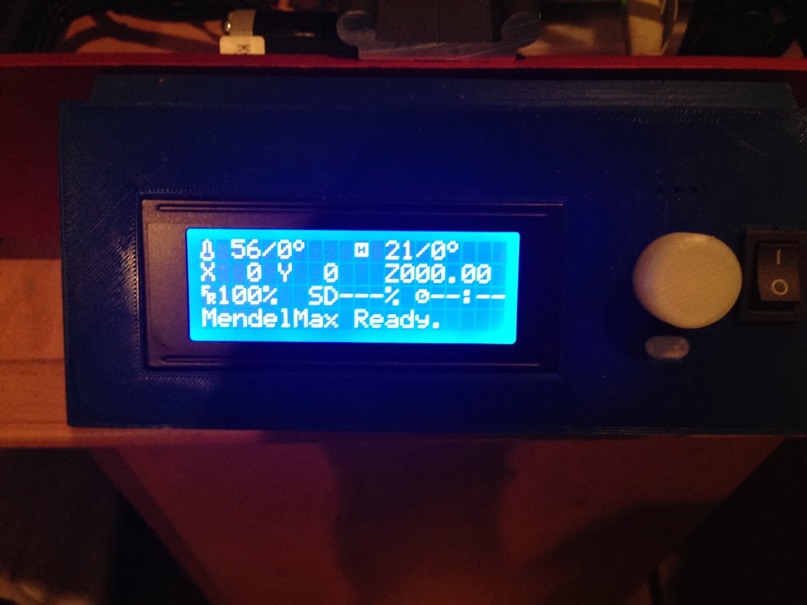
I have been running into issues where I couldn't get my Rambo electronics to work with my Smart LCD screen in Marlin. It worked fine when I had the screen hooked up to Rumba but when I switched over to Rambo, I just had a series of white boxes instead of the normal display:
I had some hope when I came across a forum post where they detail how to get the LCD support working with Polygonhell's Repetier firmware but not Marlin, which is what I am more familiar with.
I went with the non functional LCD screen for several months but recently, I came across a nice post by Os1r1s and an alternative build by John Oly that claimed to get the Smart LCD working with Rumba and Marlin. To my dismay it did not initially work until I noticed that Os1r1s specifically mentioned using Arduino version 0023 and not the most current version. I downgraded and replaced the newer pins_arduino.c file here: arduino-0023/hardware/arduino/cores/arduino.
After restarting the Rambo board, the screen worked perfectly!
I was able to reproduce the white boxes with taking the exact same firmware and putting it back on the newest version of Arduino so it is clearly an issue with the software. Halopend, on the SeeMeCNC forums solved this problem on the latest version of Arduino by replacing pins_arduino.h with this updated file here:
I wanted to install an LCD screen on my 3d printer so that I could run it from SD cards without a computer constantly needing to be plugged in. I was inspired a great deal by a panel mount that Ohm Eye developed but I have a reprap discount LCD which will not fit Ohm Eye's configuration. I saw a different case by Wersy where it was designed for the correct LCD/SD card combo I have but it fit on a Prusa Mendel. Through the wonders of 3d modeling I created a mashup that had the best of both worlds.
The front has the LCD, a click wheel and a reset button (white oval below wheel). I also added a power switch to easily flip the power to the power supply on and off. The power comes in from the outlet to a fuse at the back of the printer. The 120 V then hooks up to the switch like this:
The front of the mendel max has 4 holes so I wanted an accompanying 4 holes in the panel mount as well. Unfortunately, since the model is printed layer by layer with that front face on the bed, this created a problem since the panel curves at an angle.
See what I mean? Since it will be printing the upper hole supports last, unless the stripes went all the way up, there would not be a way to support the upper tabs (without the support feature turned on in slic3r). This works great except that with the supports going across there isn't a good way to get the LCD in! To solve this problem, I inserted the LCD while it was printing. I waited until the print had finished 60% and just dropped it in.
I was lucky because had I mis-engineered the box and needed to print a new one, this wouldn't be the easy to remove without breaking the box. A messed up box wouldn't do me any good anyways so it probably would have been okay to break at that point if I had issues.
Configuring the firmware
I have been primarily using Marlin as my firmware so after installing the LCD I set the following settings and booted it up:
#define MOTHERBOARD 301
#define REPRAP_DISCOUNT_SMART_CONTROLLER
Unfortunately, it appears as if there is an incompatibility with the combination of RAMBO, reprap discount smart controller and Marlin because my screen just displayed a series of white boxes:
I at first thought it was a bad solder point or cable installation. Installing a specially modified version of Repetier that was set up by folks over in the Rostock Max forums corrected the issue. I think the click wheel works and that it is just the screen itself but there are enough differences between Marlin and Repetier that I can't figure out what to copy and paste yet. I am still stumped by this problem so let me know if you have any suggestions!
Now that I have the printer working well, I wanted to test out how intricate I could make my prints. I found these owl earrings and printed them at 10% and 20% size. My layer height was 0.1mm and the prints took 15 minutes for the small guy and 2 hours for the lager one.
It is truly remarkable how well that they came out. The smaller owl is sitting on a US dime which is 17.9 mm in diameter! These are hard to see in real life and it was not trivial to even get my SLR camera to properly focus on the objects to take a picture.
A key development that made this possible was using hairspray to get the first layer to stick. I have tried many different methods of getting it to stick:
For PLA:
1) Blue painters tape- Does an average job especially without the use of a heated bed.
2) Heated glass- I wasn't able to get this to work on my Mendel Max but I did have luck with my Prusa previously. It could be that the Mendel Max uses a different type of heat resistant glass, similar to pyrex, which requires more playing around with the bed temperature to get it right.
3) Aquanet works really well. I spray it when the bed is cold (important to potentially prevent cracking) and warm the bed up to 70 C. I am sure to check with my extruder height that I can fit 1 piece of paper between the nozzle and the bed. Then, I can just print it and forget it!
In the US the hair spray can looks like this purple one:
The only issue I have now is that the parts almost stick too much so there probably is some fine tuning of the bed temperature that could ease that issue.
Slic3r Settings for a 0.4mm jhead nozzle:
Layer height: 0.1 mm
First layer height: 0.32 mm - Important! I had troubles sticking if this first layer was too short
Fill Density: 0.3 mm
Fill Pattern: rectilinear
Perimeters: 30 mm/s
Small Perimeters: 30 mm/s
External: 100%
Infill: 80 mm/s
Solid Infill: 50 mm/s
Top Solid Infill: 30 mm/s
Support: 30 mm/s
Bridges: 10 mm/s
Gap Fill: 50 mm/2
Travel: 150 mm/s
First Layer Speed: 25%
Skirt:
Loops: 1
Distance from object: 15 mm
Brim: ~a few mm if needed on a large part
Extruder:
185 C first layer, 180 C after
Bed: 70 C
Fan: 35 to as high as your ears can take! Disable it for the first layer
Start Gcode:
M301 P21.47 I2.24 D51.36 - set this based on your printer with PID tuning!
I know that I have been slow about updating this blog but I ran into several issues with printing that I have just recently been able to solve. I'll detail the problem here and my solution and hopefully it can help someone else.
Problem 1: Randomly crashing X axis
I was getting really bizarre motions where after starting a print that was going well, the X axis would just randomly start moving in much bigger motions than it should. For example, I notice that when printing a circle that instead of printing a 0.5 inch circle suddenly it will start printing a 6" circle. This frequently happened when I would start a print and so when it tries to find the center of the bed it will go off the +X axis and start grinding on the gears.
Solution 1: Unshielded LCD cables were causing a problem
This seemed like an electronics issue so I replaced my USB cable and switched to printing from a SD card and it did not solve the problem. I was running a new RUMBA board so it was hard to find any support for this issue even in general much less for this specific board. I eventually found that removing the reprapdiscount LCD screen seemed to fix the issue. It is likely that it was interference with the unshielded cables even though mine were <30 cm.
Problem 2: Extruder randomly extruding 4x as much plastic
I thought that I was out of the woods with the X axis problem but then I ran into a new issue that I didn't have before. I would turn my printer on and start a print which would go fine. Often I'd want to tune a slic3r setting so I would stop the print and restart it several times. I noticed that sometimes my extruder would put out way more plastic than it should. At first I thought it was different slic3r settings but after doing some controls where I took the same gcode and printed it several times I discovered that the printer would just apparently squirt out different amounts of plastic with the same gcode. Here is an example where you can see one parameter on the left when it is thick and one parameter on the right which is what it should be doing.
This made me think that it was a steps/mm setting that was getting reset but I noticed that after unplugging the board for an hour or so that I could get the settings to reset and behave normally. This led me to believe that it was a flaw in my Rumba electronics themselves.
I paid more attention to the extruder motion which gave me a clue. Here is the normal extruder extrusion rate:
After printing for a while I can do the same experiment and see that the extruder is moving 4x the speed as before:
This evidence makes it seems like there is some sort of switch such as on the microsteppers that is defective and is randomly switching between microstepping and normal stepping during the print. The hitch with that hypothesis is that I get the same behavior when I hook up the extruder to a different stepper on the board which has different switches.
Solution: Purchase non defective RAMBO Electronics
After reburning the bootloader to no avail, and getting no where with reprapdiscount to actually replace the board, I gave up and purchased a set of RAMBO electronics instead. I wanted a way to directly test whether it was the RUMBA board or some other firmware issue that I couldn't think of. Boy was I impressed when I hooked it up.
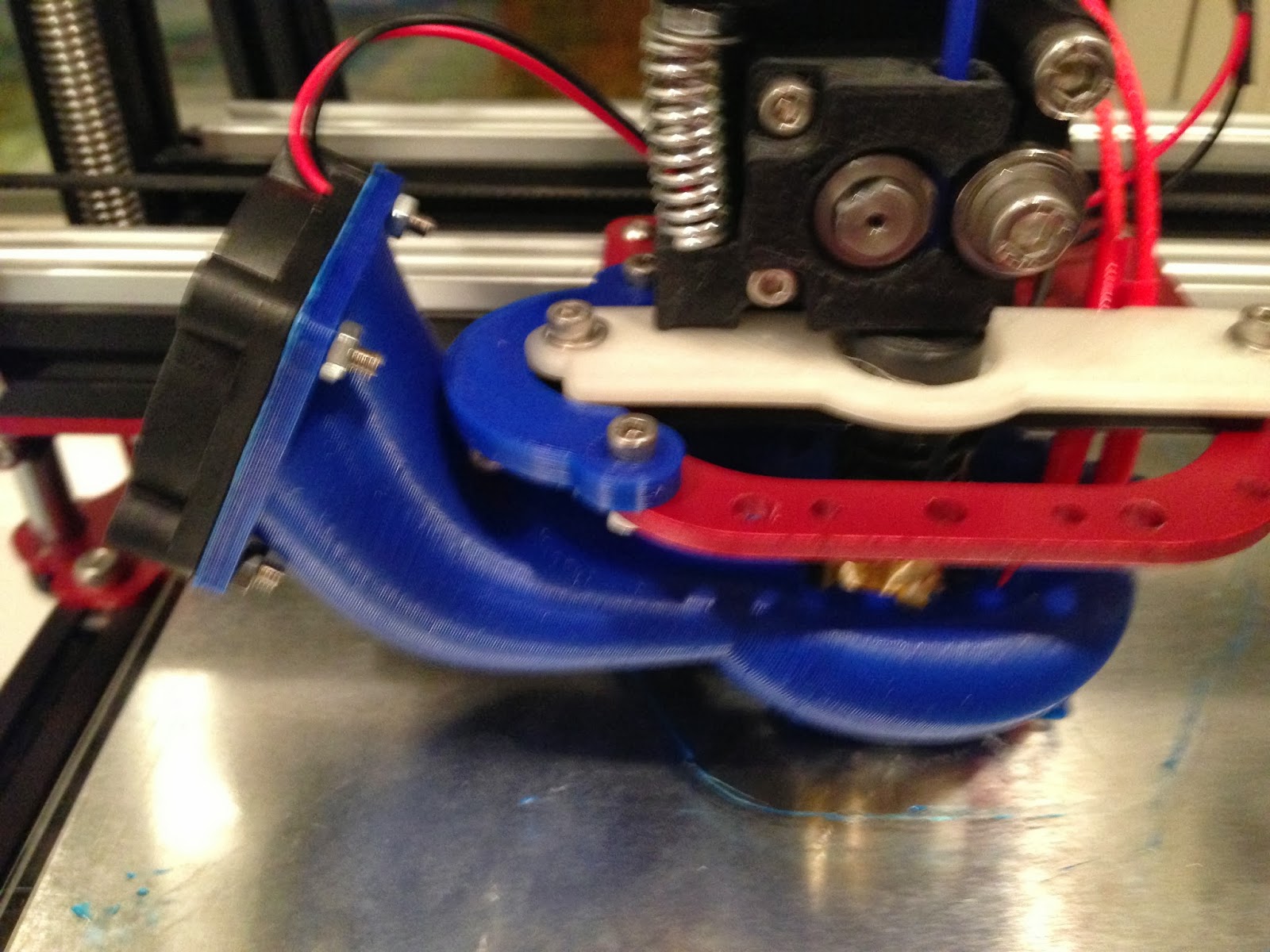
After printing a test cube that came out beautifully, check out my second print with the RAMBO electronics, the curve fan holder, with all the stock settings:
There was not a layer or boundary out of place on this print. I am just so impressed with the quality of the Mendel Max Setup now that I have the electronics working properly!
One of the most annoying things once I had everything aligned was controlling the filament feeding. I was doing it by hand but I had to constantly be checking on a print to make sure that it was feeding properly and when some prints can take 3 hours or more, it quickly gets pretty annoying to deal with. I came across a design by Garfield on thingiverse for a roll holder for the mendel max 2 that bolts to the top of the machine and accepts a 10mm tube.
Since I am in the US, metric sizes can be hard to come by but I did find a 5/16" solid rod that would fill the job quite nicely. I redesigned the ends and it worked perfectly after it was printed.
You may notice that the print quality of the left holder is horrendous and I'll talk about that more in a future post that details print errors I ran into and their solutions. Stay tuned!
The Design:
I designed these in google sketchup and started with the .stl files of the original spool holders.
1) Get google sketchup if you don't already have it! It is free!
2) Download the stl importer and put it into your plugins folder. (Mac users click on finder and type apple+shift+g and then type: /Library/Application Support/Google SketchUp 8/SketchUp/plugins)
3) Import the stl file. You will probably notice that the part is way larger than it should be. I am not sure why this is because I have mm set as my import stl unit, but I often have to scale the part down by ~0.03948 or so depending on the part. I suspect that this is the 1cm/1ft conversion factor but I am not positive. To calculate this conversion yourself just measure a distance in sketchup and then measure the same part in an stl viewer like netfabb basic.
In netfabb you click on Extras->New Measuring and then select the point-point option on the right pallette.
In sketchup you click on the measuring tape and measure the same distance. Note for this model I have already scaled it which is why both distances are the same.
4) To scale the objects, select them all using the cursor and press 's' and then type in the scaling factor.
5) Now you have your model imported and the correct size. The trouble is that you probably have way too many extraneous lines going all across the model. You need a method for stripping away all the excess lines and a different plugin called cleanup will do this. Dont forget to install the ttlib plugin that they recommend as well. I apologize if you need to make an account to download those files, but it feels a little wrong if I hosted them separately.
6) Once you have simplified the model you can start adjusting it! For the left spool holder model I show above, I was able to minimally adjust it by simply decreasing the radius of the hole. I first created an offset of the semicircle with the 'offset' button and then used the 'push/pull' feature to fill in the whole path.
7) After making all of your adjustments, you now need to export it as an stl file. I used this plugin but I am sure there are others.
8) Double check your stl file by opening it up with netfabb. I am a huge fan of repairing all stl files using cloud.netfabb.com. There is really nothing worse than printing out something with errors in it so it is really worth it to triple check that your stl files are exactly what you think they are.
9) It is also worth checking in slic3r or cura that each layer is what you expect too. In the right spoolholder version, it took several iterations for sketchup to properly export the cone that the rod rests on. At first it just eliminated that section of the design which would have been annoying to catch earlier.
For those interested here are the left and right google sketchup models.
I then pulled the marlin rumba configuration settings from Maker Tool Works. I just went through and made the necessary changes to the configuration.h file in the marlin to make it match up with the configuration.h settings from the Markers Tool Works file. I initially tried to just copy the whole file over but that does not work because apparently they used an older version of marlin.
I then just compiled and uploaded the firmware onto the rumba electronics. This is done by plugging in the rumba via USB, pressing the reset button on the rumba board, and then pressing the upload button in the arduino software.
Once uploaded, I opened up pronterface or Cura and checked to see how the steps/mm match reality.
Cura jogging interface.
Pronterface movement interface.
I told the X and Y axis to travel 100 mm and then measured what they actually traveled. It was almost spot on so then I tried the Z axis which was also correct. To make small corrections to the calibration I did the following:
Find this line in the configuration.h:
#define DEFAULT_AXIS_STEPS_PER_UNIT {80,80,1600,470} // default steps per unit for ultimaker
The numbers correspond to X, Y, Z, Extruder respectively.
To calibrate X and Y: 80/(distance it went) * (distance it should have gone)
Replace 80 with that new number you calculate to 2 decimal places and then save the file and re-upload it to the rumba. Repeat the process several times until the movements reliably go the distance you are telling it to go +/- 0.05 mm. For me, I ended up with a calibration of:
so it is quite close to the original values that I used. It took about 5x before I was satisfied with the movement.
Next, I wanted to check the extruder steps/mm setting. I measured 30 mm above the extruder and told the extruder to move 30 mm. It was spot on so I didn't bother changing that value.
I then decided to try my luck by printing off a Z end stop so that I didn't have to worry about crashing my extruder anymore. I made sure to turn off any axis homing to prevent crashes. You can find these codes in the Slic3r or Cura software. Make sure these are not in the start gcode!
G28 X0 Y0 ;move X/Y to min endstops
G28 Z0 ;move Z to min endstops
I did not previously have experience operating a printer without endstops and it definitely felt like I was living on the wild side because any false movements led to the extruder crashing into the bed or the X or Y motors going to their extents. It is important to have your hand ready to unplug it if necessary!
Due to the custom size of the Rumba endstops, there were not any available so I had to adapt Ohmeye's design for RAMPS to work with the Rumba electronics. Here are some X, Y, and Z endstops I designed that work perfectly for the Mendel Max 2.
To start I decided to use PLA as my first print material because it can be extruded at a lower temperature and does not require a heated bed. I had good luck using blue painter's tape that was just stuck on the glass top. In setting the Z height, it is important that the gap between your nozzle and the bed is ~2 pieces of paper thick. This can be a huge pain to set up initially but is easy once you have the Z endstop mounted.
Bed Leveling is another critical aspect to printing well. You can start by using a spirit level but that requires first leveling the printer itself. For precise leveling first make sure that the nozzle is at the front left and there is ~2 pieces of paper thickness between it and the bed. Next start marching across the bed in the +X axis and adjusting the two leveling screws on the front as appropriate. When looking from above, counter clockwise raises the bed and clockwise lowers it. Once you have the front edge leveled, you can start going in the +Y direction and using the back leveling screw. Do this a couple times until you feel the same amount of resistance on the paper as you drag it under the nozzle.
Start by getting the height right on the front left. The paper should have a little bit of friction in between the nozzle and the bed.
Next, go to the right front of the bed and level using the screw underneath or by twisting the Z lead screws. It is a good idea to independently level the X axis with the Z leadscrews and then leave that and just adjust the bed after.
Your first print:
Before printing out the endstop, it is better to first make sure a calibration print comes out correctly. I like this calibration set by coasterman.
1) Print out the box at 0.3 infill and check the dimensions. Is it 20x20x10mm3? If not, apply correction factors to the marlin firmware. i.e. if it is 20.1 mm in the X: 20.1/20*steps/mm=new steps/mm.
2) At this point you are probably ready to print out the Z endstop. There is a good chance that this print won't be ideal but at this point you are mostly concerned with getting a piece of plastic that will hold an endstop long enough for you to really hone your settings.
3) After you have a Z endstop in place feel free to play around with the other things in the calibration set. I particularly like the precision block because I find that models often tend to undershoot holes so this provides a way to try and fix that. The Bridge test is a more advanced one but setting it right is critical for more advanced objects. Once you have those two set up, you can try the hollow test cube and see how flat the top comes out.
Welcome to my rep rap blog! I hope to document my adventures building my second 3d printer. I have previously built a self sourced a prusa mendel 1.0. Although I eventually was able to get it printing smoothly, it took a ~6 months to iron out the bugs. Here is it printing some parts on a good day:
Here are some of the chief complaints that I was hoping to avoid the second time around:
1) The triangular design of the Prusa Mendel enables it to be very strong but unfortunately the direction that the X axis moves is exactly the direction that the printer is weakest. This prohibits faster print speeds because the frame itself has a tendency to flex.
2) I would like the possibility of printing with multiple extruders which further necessitates having a very stiff frame in the X axis as well as having enough room to fit both extruders.
3) My previous extruder was a maker gear hot end and a wades geared extruder. Although it was great when it worked, there were many times that the hobbled bolt would lose its grip or the hot end would be otherwise unreliable. The ceramic heat core is also very fragile so I am looking toward a more robust resistor or heater cartridge solution. I am looking for an extruder solution that is bulletproof in its reliability.
4) The Prusa frame is not very open and can be finicky to get everything squared up correctly. The threaded design has a tendency to come undone from vibrations loosening the nuts holding everything together.
5) I am not a huge fan of hanging the X axis from the Z lead screws because they have a tendency to pull out from the printed Z couplers. This leads to the whole X axis falling down.
6) Leveling the print bed was always a huge pain on the Prusa version 1. The design called for a plate with the lm8uu bearings and then a second plate that you actually print on that is attached to the first plate through 4 screws and springs. Although the springs are a nice buffer in case you crash your hot end, they also prohibit precise positioning of the height of the print bed so this inevitably leads to more crashes. Newer designs tend to have a fixed print bed that you level one and forget about so that is a definite must for my new printer. Also, leveling with 4 screws makes it over constrained- 3 is much better.
7) I am not a fan of 8mm rods because they flex and after using lm8uu linear bearings with the rods for about a year, the bearing actually cut trenches in the rods. Going forward I want to stick with 10mm rods and possibly migrate to a motion system where i won't have to worry about damage to these expensive rods over time. Stainless steel should be a good choice here but buying precision ground rods from Mitsumi goes for upwards of $100 for all the axis.
8) I have a preference for 24 V over 12 V so that the bed will heat up faster and the motors will have more torque. My previous heated bed was made from 120 V silicone heaters attached to a 1mm aluminum plate. This heated up quite fast and the aluminum plate helped distribute the heat evenly.
With those properties in mind I had several printers that I was considering:
1) Prusa i3
Pros: The aluminum plate makes the x axis super rigid
Cons: Aluminum plate must be custom made unless you buy it from Europe
Pros- Kit for $500 or so, linear rails make for a smooth ride
Cons- Very little support for it in the reprap community. Some people are building in buildlog.net
4) Mendel Max 1.5
Pros- Very rigid
Cons- Same triangular frame as prusa mendel
5) Mendel Max 2.0
Pros- Orthogonal frame design, All aluminum
Cons- Expensive
Coincidentally the Midwestern Reprap Festival was going to happen around the time that I was making this decision so I was able to see these printers in action. Here are my thoughts on the different types:
1) Prusa i3- Josef Prusa was there demoing his machine and although his prints were silky smooth, the printer sure vibrated like crazy while it was working! There were some people with SGraber's laser cut version of this printer that have additional stabilization pieces which seemed to help with the vibrations but I was really looking for something that was more professional in appearance. In addition, the fixed size of the x axis meant that it would be more challenging to fit a second extruder without drafting a wider frame. Finding a water jet cutter to make an aluminum version of this frame is not cheap and would run over $100 for sure.
2) Lulzbot TK-0 is a very nice printer but since it has a print bed of 300x300 mm2, the thing was just enormous and would easily take up a whole desk. They were however printing out pretty large objects with no trouble at all. Their layer heights were small and the parts looked amazing.
3) The ord bot is made out of makerslide but the connections between the rails is not great so the printer was not very sturdy. Also, the main guy selling the printer was more interested in selling bulk quantities of his motors so he gave off the feeling that the printer was just a side deal and not his real concern. Even though this kit was $400 for the mechanical stage, there wasn't really a community behind it so it seems like you would be on your own.
I was pleasantly surprised by the performance of the Roostock style printers but they are quite tall! When on a table it is about eye level and I am 6'3"! Given that I live in an apartment this probably is a little too big for my purposes but as Richrap has shown, you can print some pretty impressively large vases with it:
At the end of the day I was most struck by the Mendel Max 2.0. Maxbot's, the designer, was extremely knowledgable about all aspects of the design and it was obvious that he really did his homework in selecting each piece of the printer. The 90 degree frame made it very open and easy to get in there and the aluminum extrusions made the whole printer rock solid and it didn't flex at all. The printer uses a combination of 10 mm linear rails, and these troughs with plastic cars that slide in them.
It took about a month to arrive but here is the hardware kit unassembled:
I was going to document each stage of the build, but since it went together pretty smoothly and Maker Tool Works already made a great instruction manual with plenty of pictures it seemed a bit excessive. I had previously purchased Rumba electronics from the Indiegogo campaign so I was sort of stuck getting the Mendel Max 2 hardware kit and then I purchased the motors from ultimachine, and a 24 V power supply from amazon.com. Here it is mostly assembled:
Despite it going together well here are a few stumbling blocks I had:
For the Y axis, they provide additional sliding inserts that have a tighter tolerance than the ones they provide. You attach the inserts by pushing them in and they secure with a little knob on the back of the insert that goes into a hole in the pillow block. The problem is that this knob is off centered so when you trim the inserts to size, you have to trim them from the correct side or else they won't fit into the pillow block! My recommendation is to test fit the uncut insert first and mark which side needs to be cut.
It took a bit of patience getting the Z copper sliders to work nicely. The instruction manual has a nice part about how you need to work the copper bearings on the rod to increase their diameter. This is critical because although just 1 slider will go fine, it gets harder as you couple more together. For example, it has you tie two of them together on a side and I had to really play with the bearings to get them to slide nicely. It was the same thing once the whole X axis was assembled and you were trying to coordinate 4 bearings moving. Once set up however, they slid like a dream with almost no friction so just be patient!
Setting up the X troughs that the cars slide in to move the axis is a little confusing. It appears that they clarified the manual since I assembled it, but it is important not to modify the cars with the bowed plastic because they are indeed supposed to be bowed. I thought it was a defect and I bent them to be less bowed and consequentially offer less resistance, whoops!
Using custom RUMBA electronics had several other issues:
The electronics mount they provide is only for RAMPS so Rumba folks are out of luck. The universal electronics mount they provide with their STL files does not fit the RUMBA either so I am in the works of making a new one. I plan to take the enclosure by rznag and add some tabs so it can be bolted to the frame.
Keep in mind that the max cable length for the LCD screen is 10cm. I placed the electronics in the back of the printer, which is what is recommended but the LCD cable length will not reach to the front where I'd like to put the LCD.